 |
 |
 |
| RU |
|
Login
Newsletters
There is no newsletter category found. Information
|
Dual impedance digital multimeters Whats the point?The New Fluke 289 Digital Multimeter (DMM) offers a new feature designed to make electrical measurements easier and more reliable. This application note describes what dual impedance means to the troubleshooter and why it helps to have this functionality built in to your multimeter. Impedance basicsMost digital multimeters sold today for testing industrial, electrical, and electronic systems have high impedance input circuits greater than 1 megohm. In simple terms this means that when the DMM is placed across a circuit for a measurement, it will have little impact on circuit performance. This is the desired effect for most voltage measurement applications, and is especially important for sensitive electronics or control circuits. Older troubleshooting tools such as analog multimeters and solenoid testers generally have low impedance input circuitry around 10 kilohms or less. While these tools aren’t fooled by ghost voltages, they should only be used for testing power circuits or other circuits where the low impedance will not negatively impact or alter circuit performance. The best of both worldsWith dual impedance meters, technicians can safely troubleshoot sensitive electronic or control circuits, as well as circuits that may contain ghost voltages, and can more reliably determine whether voltage is present on a circuit.
On the new Fluke 289, the meters regular Vac and Vdc switch positions are high impedance. Use these switch positions
The new Fluke low impedance function is called LoZ volts.
Use the LoZ switch position on the DMM when readings are suspect (ghost voltages may be present) or when testing for the presence of voltage. What are ghost voltages and where are they encountered?Ghost voltages occur from having energized circuits and non-energized wiring located in close proximity to each other, such as in the same conduit or raceway. This condition forms a capacitor and allows capacitive coupling between the energized wiring and the adjacent unused wiring. When you place your multimeter leads between the open circuit and the neutral conductor, you effectively complete the circuit through the input of the multimeter. The capacitance between the connected, hot conductor and the floating conductor forms a voltage divider in conjunction with the multimeter input impedance. The multimeter then measures and displays the resulting voltage value. Most digital multimeters available today have an input impedance thats high enough to show the capacitively coupled voltage, giving a false impression of a live conductor. The meter is actually measuring voltage coupled into the disconnected conductor. However, these voltages, at times, can be 80-85 % of what the “hard” voltage should be. If not recognized as a ghost voltage, additional time, effort and money will be lost troubleshooting circuit problems. The most common places to encounter ghost voltages are blown fuses in distribution panels, unused cable runs or electrical wiring in existing conduit, open ground or neutral on a 120 V branch circuit or in card cages where 120 V control circuits are used to control assembly line or conveyor functions. Some amount of ghost voltage can be coupled from the hot side to the open side across the blown fuse. When facilities or buildings are built and wired, its very common for electricians to pull extra wire through the conduit for future use. These wires are typically left unconnected until needed, but are subject to capacitive coupling. In the case of the control circuits, these circuits are typically located adjacent to unused control lines, thereby creating a potential for a ghost voltage measurement. Absence or presence of voltage testingTraditionally most electricians and plant maintenance professionals used some form of solenoid tester to determine whether circuits were energized or not. Because of their low impedance circuit, solenoid testers are not fooled by ghost voltage. These testers did their job back in the day but they rarely comply with the current IEC 61010 safety standards and current North American regulatory requirements. They should not be used for troubleshooting purposes in high energy three phase distribution panels or for testing whether a circuit is energized.
The Fluke 289s LoZ function has a low input impedance, on the order of three kilohms. When the leads are placed on an open circuit that contains a ghost voltage, the low input impedance will cause the ghost voltage to dissipate and the meter will display a reading near zero volts indicating no voltage present. When the leads are placed on a live circuit, however, the input senses the presence of hard voltage and then displays the actual voltage present. SummaryGiven the variety and complexity of measurement and testing requirements found in most facilities today, a meter with a dual impedance input offers the troubleshooter or technician more flexibility to cover applications or measurement needs ranging from basic voltage testing to troubleshooting sensitive electronic circuits. Issue: KIPiS 2008 #5 Related Information:
Companies' news
KIPiS articles
|
Current issue
Search
|


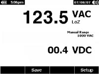
 LoZ stands for Low Impedance (Z). This feature presents a low impedance input to the circuit under test. This reduces the possibility of false readings due to ghost voltages and improves accuracy when testing to determine absence or presence of voltage. This feature also automatically determines whether the measured signal is ac voltage or dc voltage, selects the correct function and range, and displays the correct information.
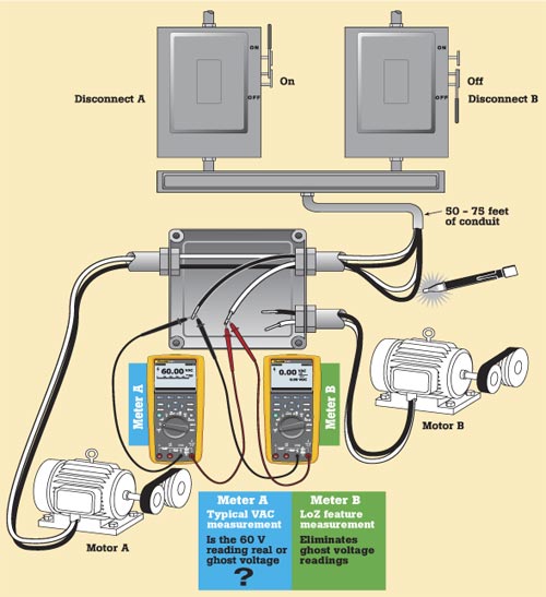

|
|
| © "Test & Measuring Instruments and Systems" ("KIPiS"), 2000-2024 |
