 |
 |
 |
| RU |
|
Login
Newsletters
There is no newsletter category found. Information
|
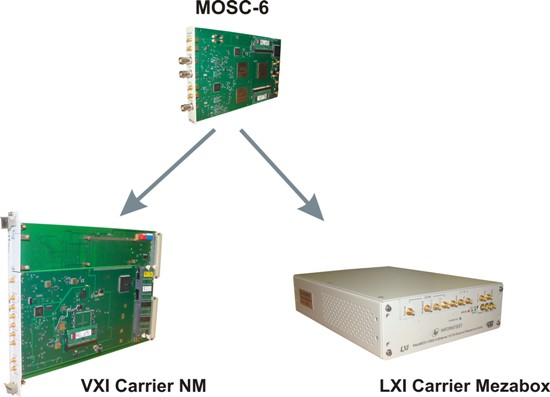
Holding Informtest announces new digital oscilloscope module MOSC-6 10/06/2011 M-module MOSC6’s intended to work as digital oscilloscope or fast digitizer in informational measuring systems based on two different measuring platforms: VXI bus and LXI. M-module is implemented as a mezzanine of triple width that can be installed onto mezzanine carriers for VXI (NM-VXI) and LXI (Mezabox-1, Mezabox-2), which connects to it, via Local informational bus.
M-module has two measuring channels. Each measuring channel can perform measurements of input signal with maximum span from -50 V to 50 V. The entire span is divided into 11 sub-ranges from ± 25 mV to ± 50 V. Vertical resolution in each range is 8 bit. Minimal period of discreetness for each measuring channel is 200 ps, which is equal to maximum sampling frequency of 5 GHz. The module has a control over setting of a discreet period. Full sweep is determined by sampling period and maximum size of RAM, which is 1024 Mb (1024M counts) per channel.
The bandwidth of a measuring channel – not less than 900 MHz. The module has a function of limiting the bandwidth with a controllable analog Low- Pass Filter with cut-off frequencies 300 MHz and 20 MHz. The filter is turned on/off through the software control panel.
The module has a synchronization channel intended for synchronization of oscilloscopes performance from external trigger signal. Maximum span of an input signal is from -5V to 5V. Level of synchronization is set through software. For simultaneous work of a number of MOSC-6 modules, included into a system, there is a dedicated SMB connector on a front panel, through which the module can send a trigger signal. There is an option for the MOSC-6 to operate from external 10 MHz clock frequency generator, which is converted by the module into a clock frequency of 2.5 GHz. Its necessary for simultaneous synchronization of a number of oscilloscopes from a one generator. One of the oscilloscopes can take on a role of the generator. For synchronization there are two separate SMB-connectors on a front panel: one for input frequency, and one for output. Theres also an internal generator of calibrating signals that allows performing calibration and self-test of the module.
Technical Characteristics
Accuracy of an internal reference frequency not less than 0.00025%(2,5 ppm). The module has an option (controlled through the software) of setting a DC input to open or closed mode. Maximum RAM size is 1024 Ms readings per each measuring input. An option to set programmable limit to the amount of logged in a single measurement data from 1K up to max. with a step of 1 K.
Triggering sources: - Program (Software)
Triggering parameters: - Waiting/auto modes, synchronization from front or from cut, by parameter of a window, pulse width, by a quantity of starting events;
Holding Informtest
Related Information:
Companies' news
KIPiS articles
KIPiS News & Events
|
Current issue
Search
|


|
|
| © "Test & Measuring Instruments and Systems" ("KIPiS"), 2000-2024 |
